KT.← Selected work

AERO 465 / Senior aerospace lab / 2025

GORDON
Autonomous
Nerf Turret.

An autonomous target-detection and engagement demonstrator combining ultrasonic sensing, encoder feedback, embedded control, custom mechanical hardware, and a physically actuated Nerf blaster.

3-person team4 weeks$25 budgetMechanical designMechatronics

Four weeks.
Three people.
$25.

GORDON started as our final project for AERO 465. The requirements were open-ended: integrate at least four devices into an aerospace-related system, finish within a month, and stay inside a $25 project budget.

We decided to make things a little harder for ourselves. Our idea was an autonomous Nerf turret that could scan its environment, detect a target, determine its angle, physically rotate toward it, verify its orientation using encoder feedback, and fire without manual input. We had four weeks to make it work.

3Team members
4Weeks of development
$25Hard budget
180°Scan
80 / 40 cmTracking / engagement

Making the subsystems
become one system.

My role sat heavily at the interfaces between mechanical hardware, electronics, and software.

01

Mechanical

  • SolidWorks design
  • Custom gears and sensor mount
  • Motor, trigger, and blaster hardware
  • Rotating platform co-design
02

Electrical

  • Overall wiring and electronics layout
  • Arduino, sensor, actuator, motor-driver integration
  • 12 V power architecture
  • Electrical troubleshooting
03

Software

  • Firing sequence and timing
  • 1D ultrasonic Kalman filter
  • Subsystem integration
  • Engagement logic
04

Test

  • Test-matrix creation
  • Targeting validation
  • Data collection
  • Failure investigation

Team attribution: Timothy Lunney primarily developed the ultrasonic object-detection code. Michael Beath primarily developed the platform-control code and worked with me on the orientation subsystem and rotating platform. I owned most final mechanical and electrical integration, the firing subsystem, software integration, and test-matrix creation.

From seeing a target
to actually firing at it.

01ScanUltrasonic servo sweep
02MeasureDistance samples
03Filter1D Kalman filter
04AcquireStore target angle
05OrientCommand platform
06AlignEncoder feedback
07EngageCheck distance / position
08FireSpin up, actuate trigger

The final system combined three major subsystems: detection, orientation, and firing. Individually, they could work. Integration was where their assumptions collided.

Designing hardware around components we actually had.

I designed essentially all final 3D-printed components in SolidWorks: the sensor mount, blaster mounting hardware, geared-motor integration, trigger hardware, custom gears, and the smaller parts needed to make the assembly physically coexist.

The rotating platform was co-designed with Michael and used a lazy-Susan bearing to simplify manufacturing while giving us a smooth rotational interface. The gearing had to fit the available geometry, interface with the encoder, and reduce the geared motor speed to something useful for target alignment.

OriginalHelical gears
→
FinalStraight-cut gears

We changed to straight-cut gears because they made integration and rapid prototyping much more direct. The target reduction could be set by choosing an integer tooth-count pair, then translated into a predictable gear diameter and center distance while we revised the motor location and platform geometry. That made it quick to print a new pair, test the mesh, adjust the ratio if needed, and reinstall the hardware. Compared with the helical concept, the straight-cut geometry also avoided axial loading and removed helix alignment as another variable during assembly. For this prototype, that simpler relationship between tooth count, ratio, and packaging was more valuable than the smoother, quieter mesh of helical gears.
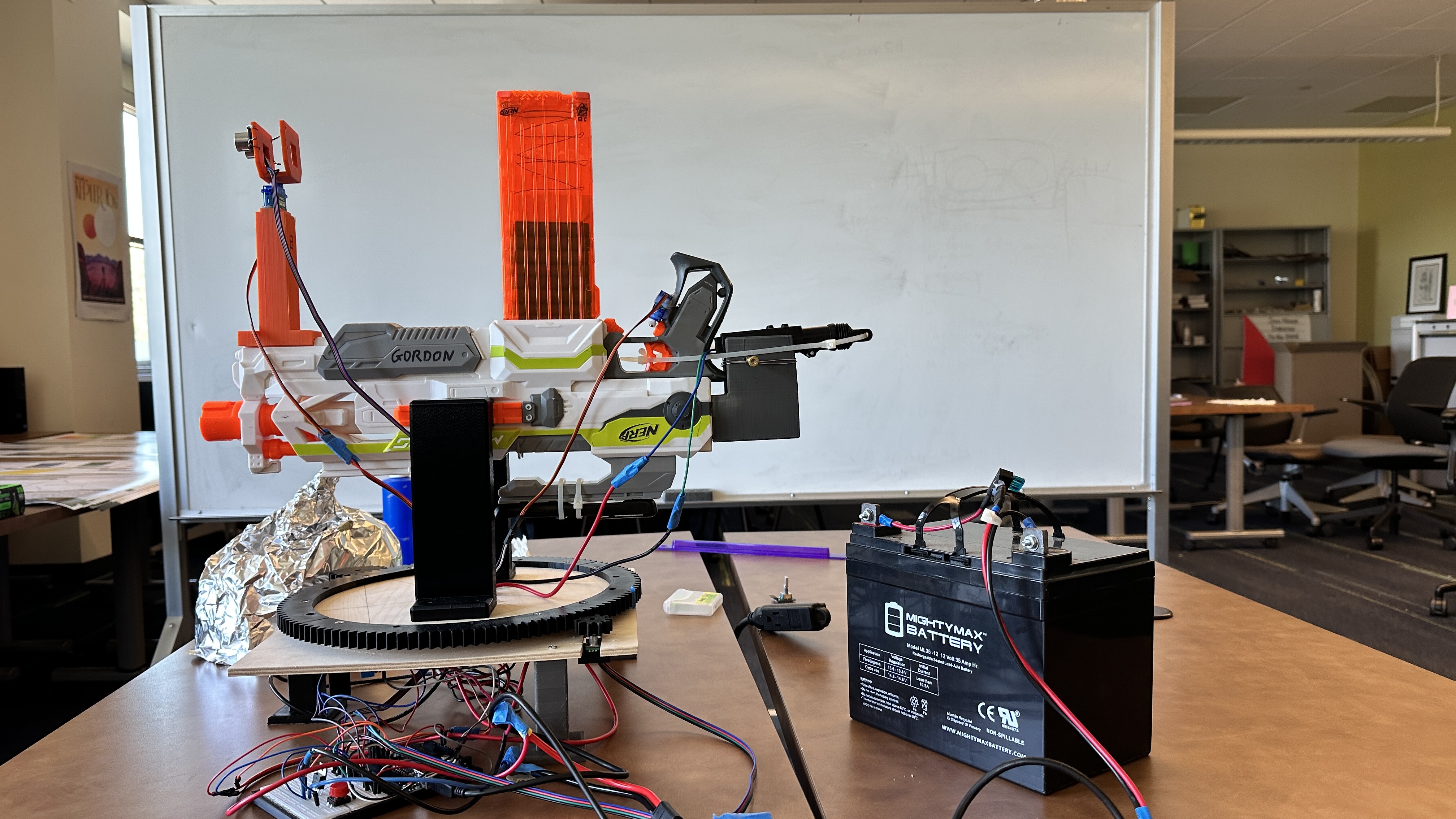
Complete GORDON assembly with rotating platform, wiring, and 12 volt battery
Full system view: the rotating platform, 3D-printed integration hardware, prototype wiring, and 12 V power supply in one assembly.

01 / Find
the target.

The detection system used an HC-SR04 ultrasonic sensor mounted on an SG90 servo.

The servo swept through 180° while distance measurements were collected. I implemented the 1D Kalman filter used to stabilize the ultrasonic measurements and integrated it into the final detection logic. When an object entered the 80 cm tracking range, the system stored the corresponding servo angle and passed it to orientation.

SensorHC-SR04 ultrasonic sensor
ScanSG90 servo / 180° sweep
Decision80 cm tracking / 40 cm engagement

02 / Turn
detection into motion.

A 12 V geared DC motor rotated the platform while a rotary encoder measured angular position.

The control logic was intentionally simple: determine orientation error, command the motor in the appropriate direction, and stop once the error entered an acceptable deadband. This was closed-loop positioning with encoder feedback, not PID control.

Michael primarily developed the platform-control code. I helped establish requirements, design the mechanical integration, debug closed-loop behavior, and bring the orientation subsystem into the complete system.

Target angle→Position error→Direction command→H-bridge→DC motor→Platform→EncoderError-based direction control + deadband / not PID

03 / Fire.

This was my subsystem.

I owned most firing-system development and integration. The logic first spun up the Nerf blaster flywheels; after a delay for them to reach operating speed, the trigger actuator fed the dart into the flywheels. I wrote the firing-sequence code and integrated the engagement conditions, flywheel control, actuator timing, and physical trigger mechanism.

The code was the straightforward part. The mechanical trigger was where things became interesting.

ConditionEngagement criteria met
SequenceFlywheel spin-up delay
ActuationAutomotive actuator / trigger linkage

And then the ideal design
started falling apart.

The messy parts were not side stories. They were the engineering story.

Problem 01

The actuator cost more than the entire project.

The linear actuator we wanted was around $40. Our entire project budget was $25. I started looking for anything else that could provide the same short linear motion and landed on an automotive door-lock actuator. Cost: about $3.

Problem 02

Problem solved... until it wasn't.

The door-lock actuator worked, then its startup current spike killed our original 12 V supply. We needed 12 V with much more current capability. The practical answer was a car battery, plus a fuse. It powered final testing and demonstration, after temporarily rendering our transportation unusable.

Problem 03

Then the actuator worked a little too well.

The actuator was fast enough to move the trigger before the dart could feed correctly into the flywheels. The final fix was zip ties with carefully tuned slack. That small mechanical delay gave the dart time to feed and made the firing sequence reliable.

Burned MOSFETsFaulty breadboardFailed 12 V supplyTrigger jamsRotating wiringGear integrationScope reduced to 180°

Three subsystems.
One machine.

Detection, orientation, and firing were developed separately. The final demonstration required all three to agree on what happened next.

I performed the overall software integration while also integrating the physical hardware and electrical system those software blocks commanded. Sometimes a software problem was wiring. Sometimes a mechanical problem was timing. Sometimes the component itself was bad.

GORDON system demonstration. The final sequence brought detection, platform alignment, engagement logic, flywheel spin-up, and trigger actuation into one physical system.

Making it work was step one.
Measuring it was step two.

I created the project test matrix to evaluate combined targeting performance.

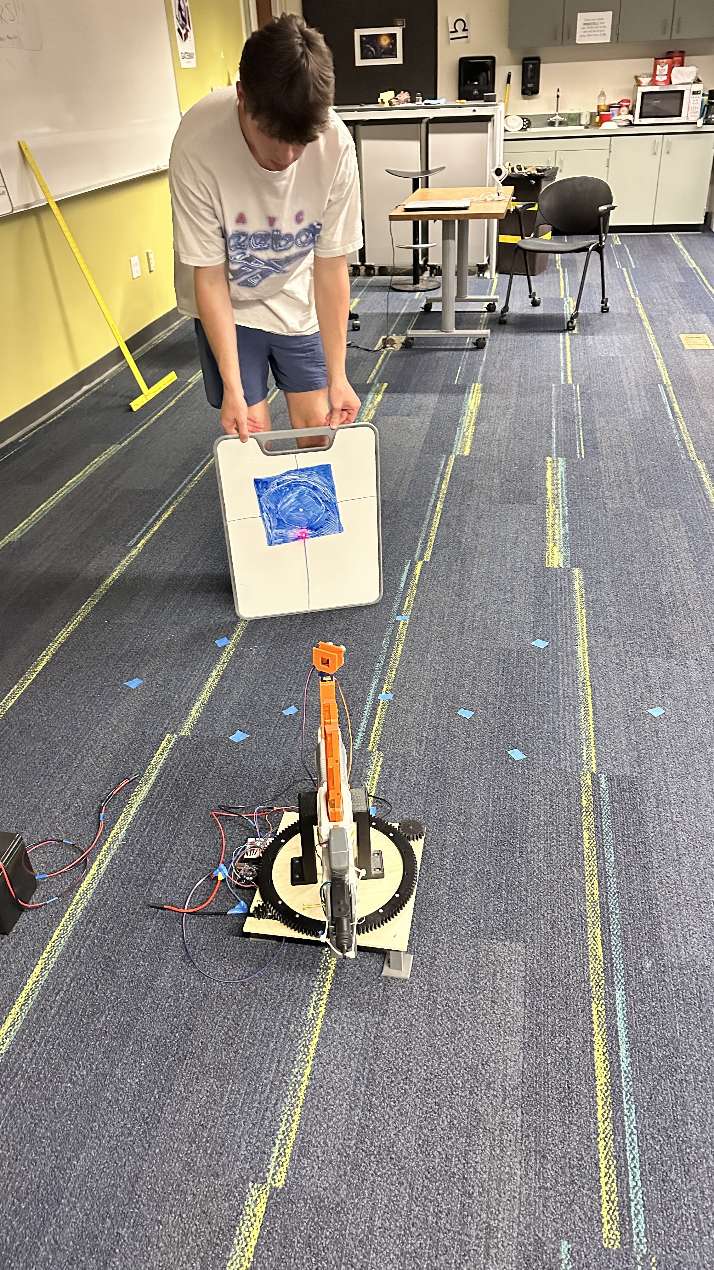
A laser pointer mounted parallel to the blaster barrel provided a consistent targeting reference. For each trial, the target was placed at a predetermined location, GORDON detected and aligned itself, and we measured deviation from the intended target center.

0°+30°−30°+60°−60°

A system-level test.

The measurement included the combined effects of sensing, target-angle determination, gearing, platform motion, encoder feedback, mechanical assembly, and firing alignment.

Timothy Lunney preparing the target board for GORDON's target-alignment validation
Timothy Lunney preparing the target-alignment validation setup used to evaluate combined sensing and positioning error.

Testing found the next problem for us.

>7 in

Early trials remained relatively close to target center. As testing continued, positioning error became progressively larger; later trials exceeded approximately seven inches of deviation.

The prototype was not fully resetting or recalibrating position between acquisitions, so small errors accumulated across sequential trials. The four-week schedule did not leave time for a larger repeated-trial dataset. These results validate the prototype while clearly identifying the next engineering problem.

Before more features,
fix the fundamentals.

Priority 01

Reference

Add an absolute or repeatable position reference to reduce accumulated orientation error.

Priority 02

Wiring

Improve routing and harness management around rotating hardware.

Priority 03

Filtering

Revisit filter implementation and sampling strategy for faster distance response.

Priority 04

Power

Build a cleaner, more robust prototype electrical architecture.

The part of GORDON I remember most.

What stayed with me was not simply getting an autonomous Nerf turret to work. It was how quickly the engineering changed every time we left the ideal case: the actuator cost too much, the replacement actuator killed the supply, the new source fixed that, then the actuator created a timing problem. The gear design changed. MOSFETs burned out. A faulty breadboard sent us looking in the wrong direction.

  1. Figure out why it failed.
  2. Look at the hardware and resources we actually had.
  3. Find a practical workaround.
  4. Test it.
  5. Keep iterating until the system behaves reliably.

Sometimes the solution was software. Sometimes it was a redesigned part. And sometimes it really was a car battery and a few strategically placed zip ties.

Technical evidence,
not a random gallery.

Select any photograph to inspect its full framing.