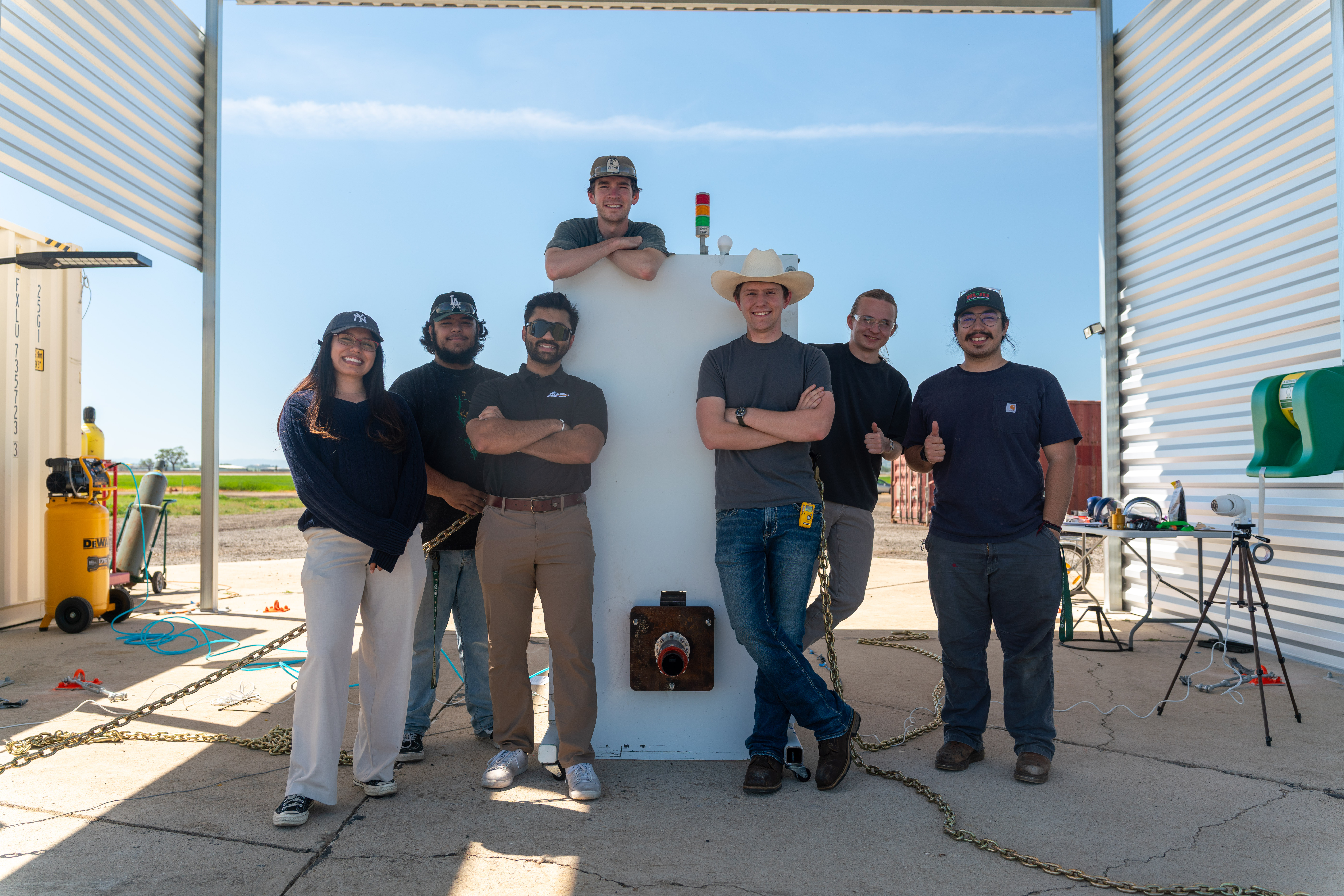
SLO Propulsion Technologies / September 2024 to present
NILE
Test Stand.
A modular liquid-engine test stand redesigned to support testing of an eventual ~1,000 lbf N2O / isopropyl-alcohol engine.
01 / Project brief
From a 100 lbf concept
to a real test capability.
NILE began with students who wanted to apply propulsion concepts from the classroom to real liquid-engine hardware and who saw a need for an R&D-style test capability where students could explore different bipropellant-engine configurations.
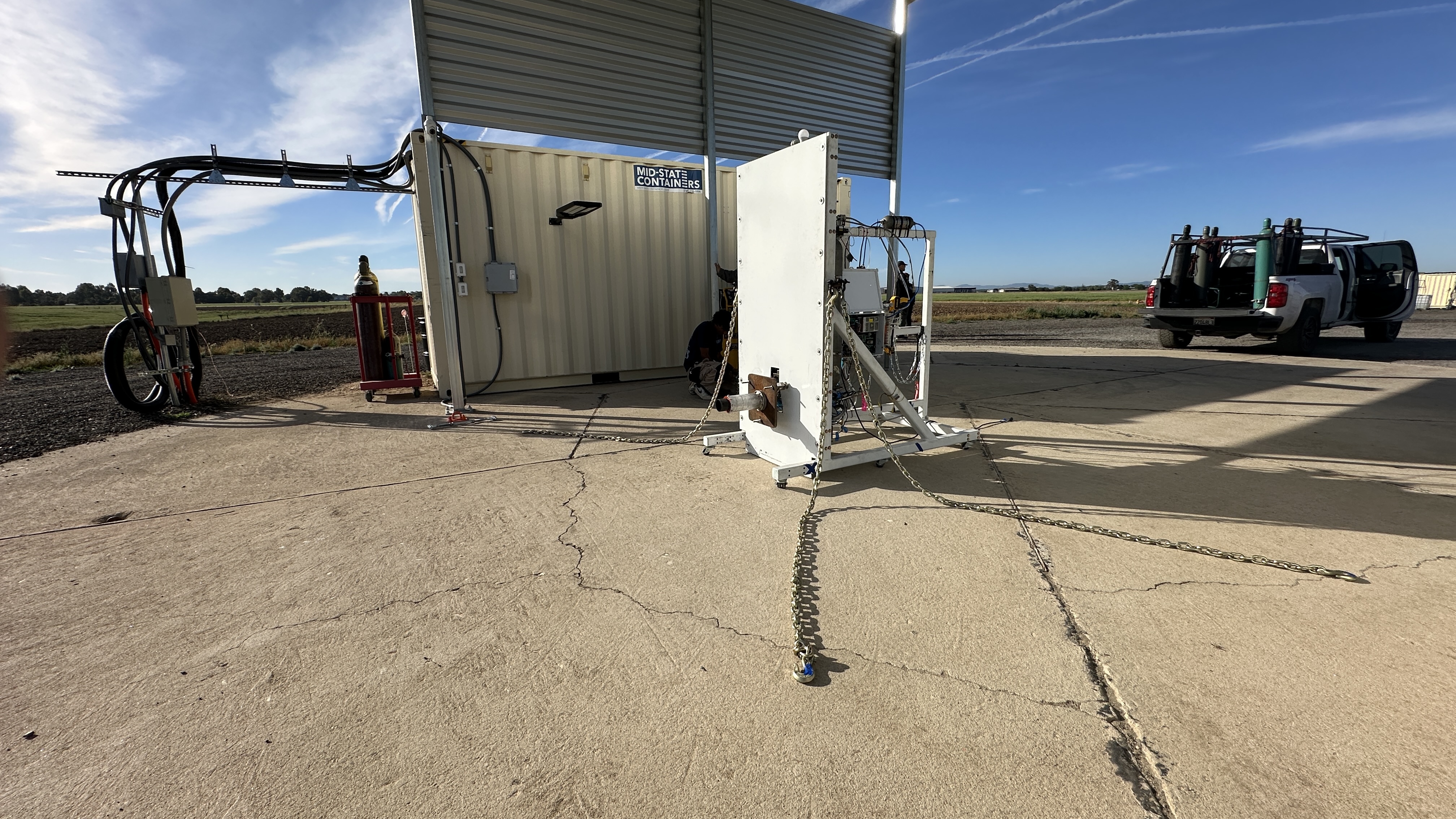
That ambition included concepts such as thrust vectoring, engine throttling, and regenerative cooling. The existing Cal Poly propulsion facility could not support that level of flexibility or scale, so the university provided access to an off-campus test site. I helped develop the stand and its deployment approach around the structural, operational, and safety requirements that site and test program demanded. I inherited a stand concept for a much smaller engine and redesigned essentially the entire structural and mechanical architecture as NILE grew toward a ~1,000 lbf design target.
02 / Structural architecture
A clear load path
to the ground.
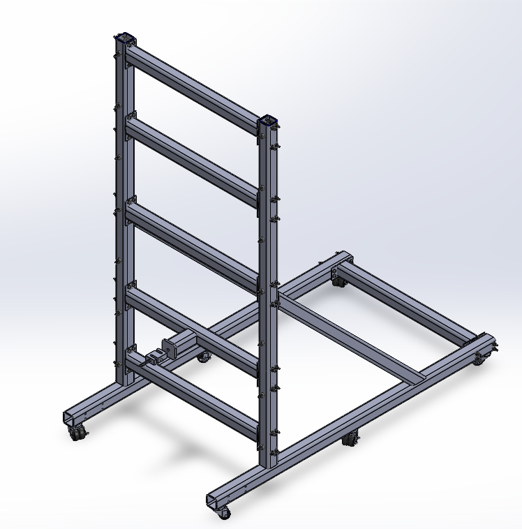
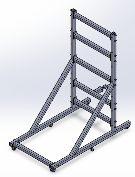
The final stand used two symmetric welded L-shaped side frames with ~45° diagonal braces, bolted cross-members for modularity, and extended “paws” to enlarge the support footprint. I owned the SolidWorks structural design, engine mounting, thrust members, blast shield, brackets, manufacturing drawings, and mechanical integration.
03 / Analysis drove redesign
The calculation
changed the hardware.
Hand calculations and MATLAB scripts exposed a weakness in an early single-member thrust path.
A simplified 36-inch bending case produced ~49.7 ksi against the 39 ksi conservative yield comparison. That analysis motivated a redesigned engine interface with two structural thrust members and three radially spaced axial S-load cells. It improved the load path and thrust-measurement integration; it was not a claim of a perfectly equal load split or a final FEA validation.
04 / Build and integrate
Designing for
the hardware that exists.
The structure had to work with manufacturing constraints, fluid routing, maintenance access, and an evolving test program.
I coordinated welding, machining, waterjet work, procurement, assembly, and manufacturing schedules. As the fluids geometry matured, I worked with the fluids team to relocate and remake brackets that would otherwise have forced poor tubing bends or limited valve access.
05 / Test operations
Cold flow first.
Then fire.
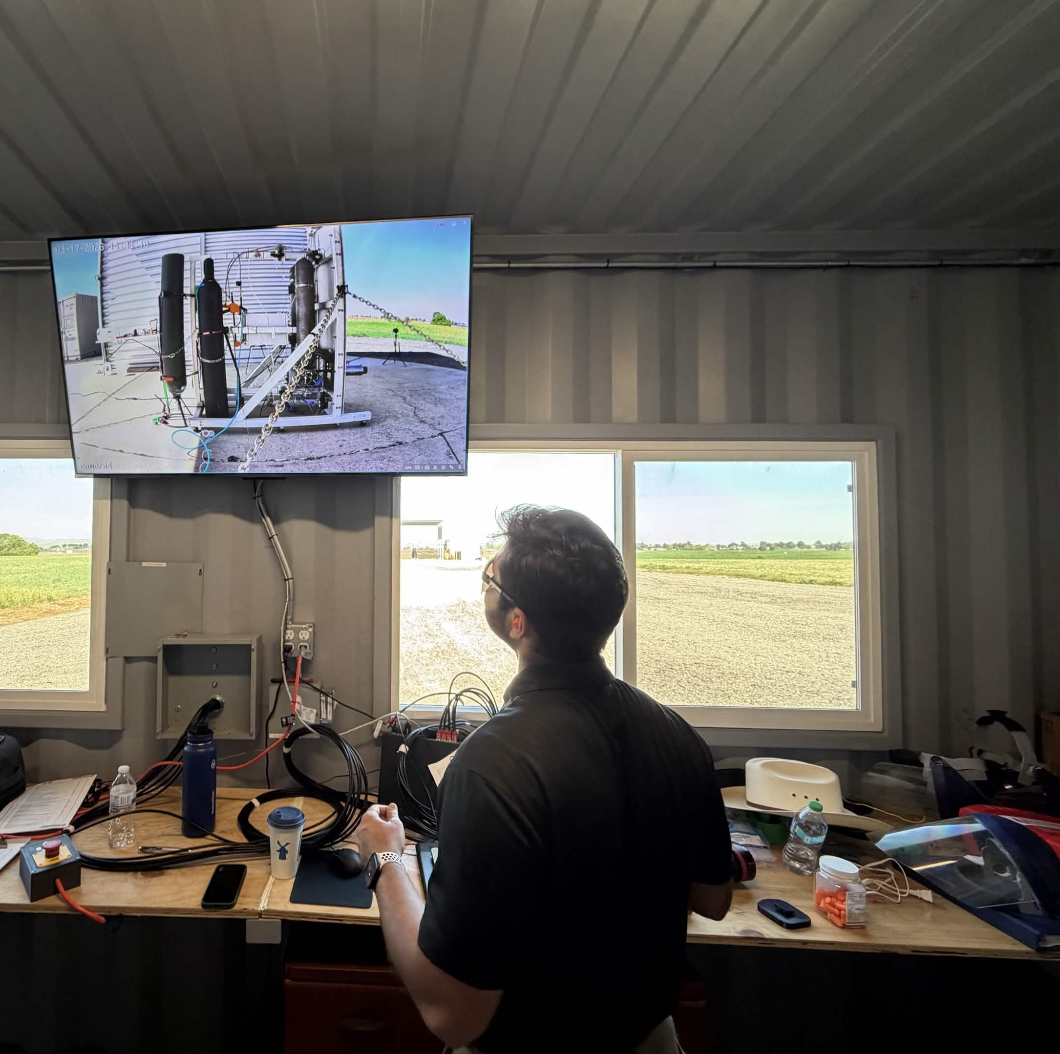
I remained involved through hydrostatic testing, cold-flow testing, hot-fire operations, post-test inspection, and safety planning.
As testing progressed into cold-flow and hot-fire operations, I served as Chief Safety Officer. I helped establish test constraints, support abort procedures, coordinate remote camera coverage and bunker operations, and manage day-of-test safety with the multidisciplinary team.
06 / Off-nominal learning
Measure the event.
Inspect the hardware.
~4,200 lbf
Indicated load at instrumentation saturation during a hard-start transient.
The actual transient peak is unknown. The event was not a controlled proof test. Post-event inspection found no visible frame damage, loosened joints, weld cracks, or buckled structural members; the load-cell / engine-interface plate required replacement.
07 / Safety and leadership
Test readiness is
an engineering discipline.
As Chief Safety Officer, I helped establish test constraints and coordinated day-of-test safety during operations involving up to ~15 engineers.
The test plan accounted for high-pressure failures, leaks, invisible alcohol fires, electrical hazards, debris, and structural or propulsion-system failure. The blast shield was integrated to help protect critical feed-system hardware from potential engine fragments.
08 / The team
Design, build,
test, iterate.
NILE brought structures, fluids, electronics, and software into one operating test system. My role evolved from Structures Lead to Technical Director and Chief Safety Officer while coordinating the interfaces between them.